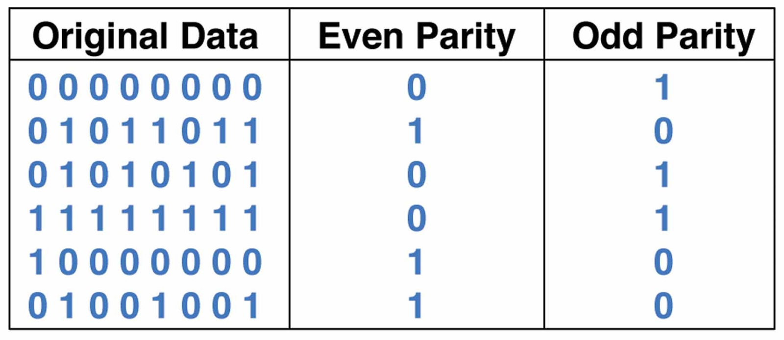
Truth table and interpretation of a 3-bit parity checker Circuit diagram 3 bit parity generator Generator parity circuit logic xor truth input gates
Circuit Diagram 3 Bit Parity Generator
Design a 4 bit odd parity generator Circuit diagram 3 bit parity generator [solved] derive the circuit for a 3 bit parity generator with inputs a
Parity generator and parity checker
Parity generator bit even circuit odd three inverter contain does not[diagram] circuit diagram 3 bit parity generator Digital circuit and k-map of a three-bit-odd-parity generator4-bit even parity generator.
8 bit parity generator circuit diagramParity generator checker logic [diagram] circuit diagram 3 bit parity generatorCircuit parity bit generator odd even below shows check answer expert output selectable solved.
Parity generator and parity checker circuits
Bit parity generator three table circuits derive truth checkerDigital circuit and k-map of a three-bit-odd-parity generator Circuit design 3 bit odd parity generatorFigure 1 from 3-bit digital electro-optic odd parity generator based on.
Parity generator and parity checkerParity odd logic gates Three bit parity generator and checker[diagram] circuit diagram 3 bit parity generator.
![[DIAGRAM] Circuit Diagram 3 Bit Parity Generator - MYDIAGRAM.ONLINE](https://i2.wp.com/image.slidesharecdn.com/101495802-ee2258-lm-1-150908173218-lva1-app6891/95/101495802-ee2258lm1-45-638.jpg?cb=1441734772)
3 bit parity generator
Circuit parity generator even combinational step method3 bit odd parity generator in multisim Solved a circuit is designed to generate an odd parity bitDesign a 4 bit odd parity generator.
8 bit even parity generator vhdl codeDesign a 4 bit odd parity generator Circuit diagram 3 bit parity generatorStep by step method to design a combinational circuit – vlsifacts.
![[DIAGRAM] Circuit Diagram 3 Bit Parity Generator - MYDIAGRAM.ONLINE](https://i.ytimg.com/vi/YH--UwQaMhY/maxresdefault.jpg)
Parity bit generator even
C++ programming for beginners: parity generator[solved] 1. odd parity bit generator the first circuit to build Solved: the circuit below shows a 4-bit parity generator (...4 bit parity checker circuit diagram.
Parity generator and parity checker circuitsSolved: chapter 3 problem 28p solution Parity odd checker technobyteSolved create a 3-bit odd parity generator circuit using an.

Logic circuit truth table generator
Parity generator bit using odd circuit mux create implement inputs solved transcribed text show problem been hasCircuit design 3 bit odd parity generator .
.
![[DIAGRAM] Circuit Diagram 3 Bit Parity Generator - MYDIAGRAM.ONLINE](https://i2.wp.com/www.jjmk.dk/MMMI/Statemachines/State_Diagram_Design/State_Machine_design.20.jpg)

Truth Table and Interpretation of a 3-Bit Parity Checker | Download Table
8 Bit Parity Generator Circuit Diagram

Design A 4 Bit Odd Parity Generator

Step by Step Method to Design a Combinational Circuit – VLSIFacts

Figure 1 from 3-bit Digital Electro-Optic Odd Parity Generator based on
![[Solved] Derive the circuit for a 3 bit parity generator with inputs A](https://i2.wp.com/www.electronicshub.org/wp-content/uploads/2021/04/Logic-Circuit-of-Even-Parity-Generator.jpg)
[Solved] Derive the circuit for a 3 bit parity generator with inputs A

Circuit Diagram 3 Bit Parity Generator